Using the GUI
In the first part, we’ve taken a quick look at the GUI.
Let’s now configure something using the GUI. Say add a NAT rule and a default route so that a host behind this Vyatta to access the Internet. And setup some firewall rules. Just to feel the GUI a little bit.
Adding a NAT rule
Vyatta said in their announce that the NAT rules area is to be improved over the time to provide a better way to manage and present the NAT rules.
Right now we are going to create a masquerade NAT rule on this Vyatta router’s external interface, to hide the internal subnet behind Vyatta.
From the Configuration tab, Navigation area, click the service node, click the nat sub-node, and click the Create button:
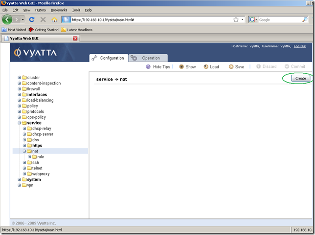
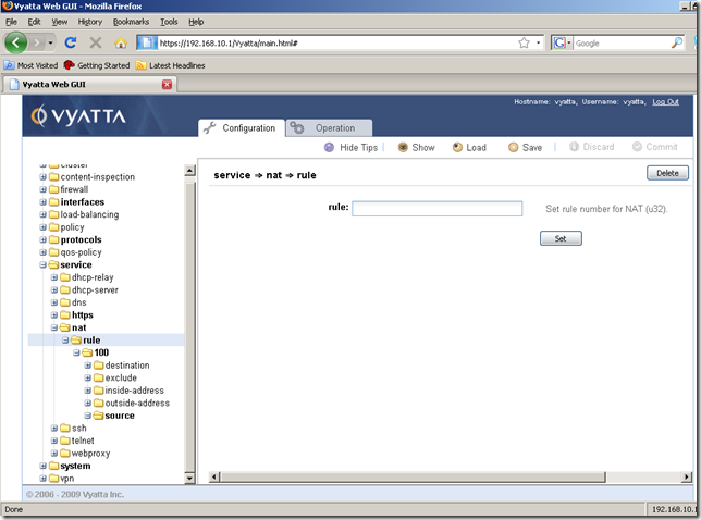
Next click rule from the nat sub-node, enter a number for the NAT rule we are about to create in the Input/Output area, and click the Set button.
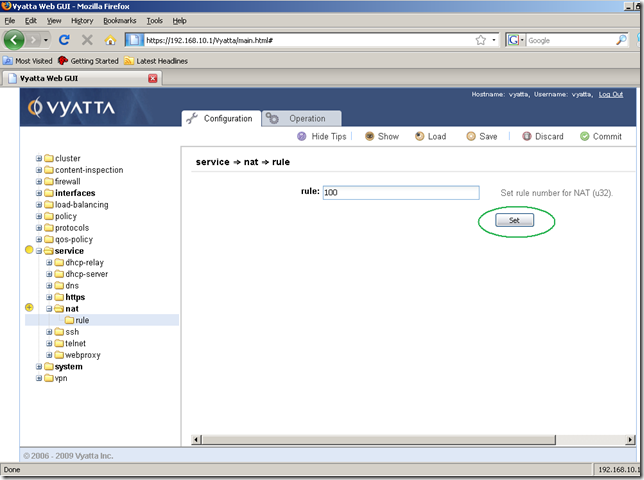
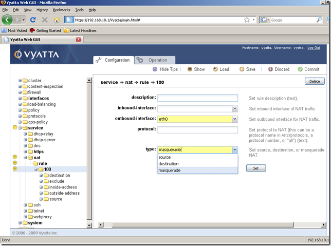
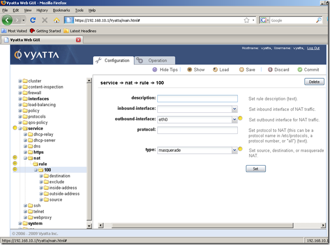
And we are automatically taken to the next screen after we’ve clicked the Set button(this is the wizard feeling I was talking in part 1). In the Input/Output area, eth0(this is the external interface for this machine) will be the outbound-interface and the type will be masquerade(select it from the drop-down menu). Click the Set button.
And the modifications were set:
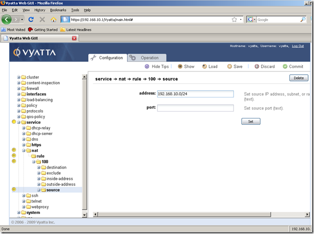
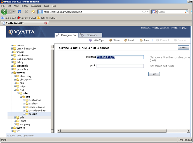
Next we need to specify the source network for this NAT rule which will be the IP subnet behind Vyatta(the subnet which we will hide behind Vyatta).
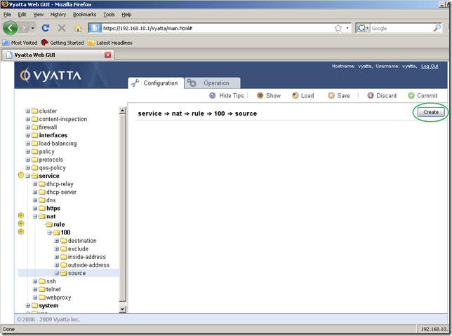
Click source from the rule 100 sub-node and click the Create button:
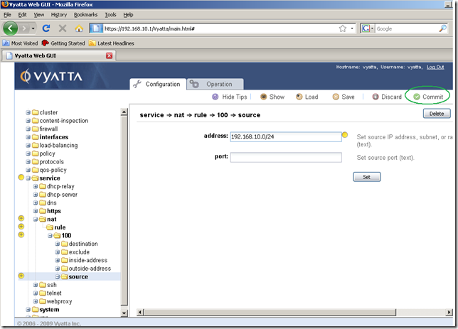
Configure the needed subnet in the Input/Output area and click the Set button:
And we’re done.
All we need to do now is to commit our configuration changes, so click the Commit button:
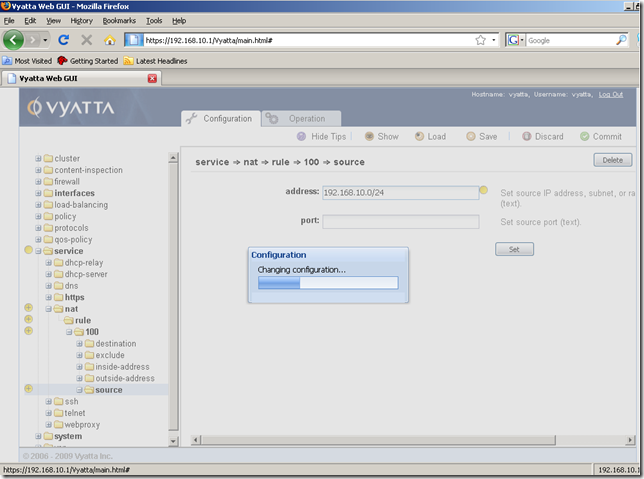
The configuration is being applied:
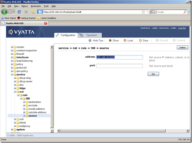
And now the configuration was successfully applied:
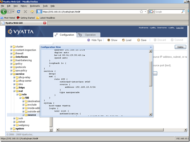
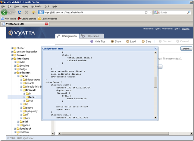
View the current configuration by clicking the Show button:
Now, say we’ve created more NAT rules and we want to modify some rules. Perhaps we want to change the number of a NAT rule. We can’t do that from the GUI(as we cannot do that from the CLI too):
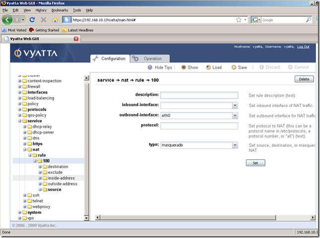
However, as can be seen we can easily edit the settings of this NAT rule(like the source address):
So be careful when numbering your NAT rules.
Also we cannot copy and paste an existing NAT rule to quickly modify it if we want to add a new similar NAT rule and speed the process a little bit.
Adding a static default route
From the Configuration tab, Navigation area, click the protocols node, click the static sub-node, and click the route sub-node. In the Input/Output area add the needed ipv4net, which is 0.0.0.0/0 and click the Set button.
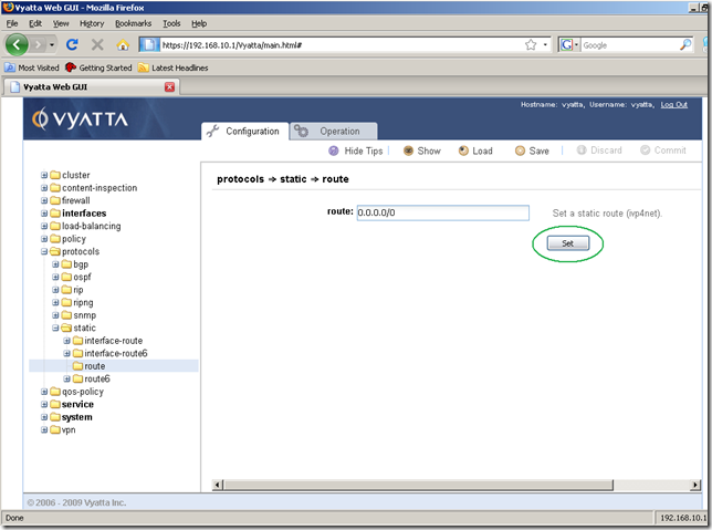
The ipv4subnet was set for this route:
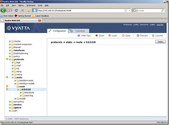
And now move to the next-hop sub-node.
From this node, the Input/Output area add the IP address of the next-hop router for this route, and click the Set button.
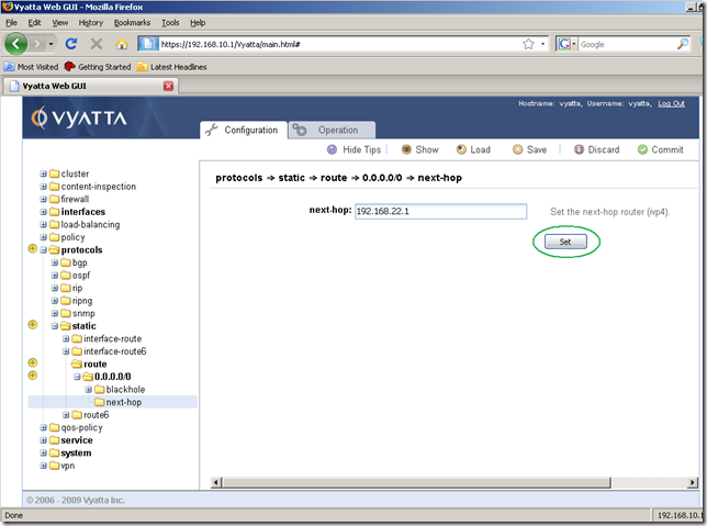
After the next-hop router for this route was set, we can Commit our configuration:
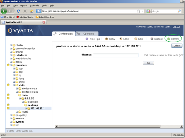
Our configuration was applied:
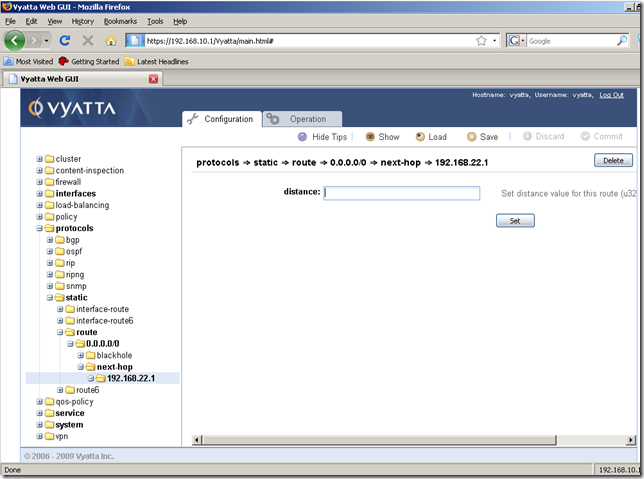
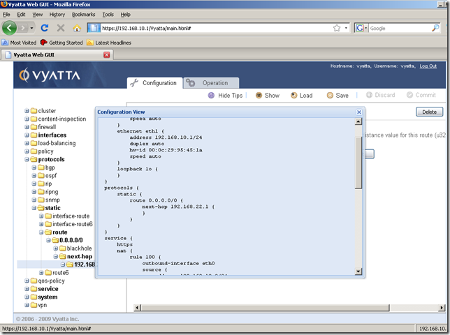
Now a host behind this Vyatta router should be able to access the Internet(we can do a quick test). And we can monitor our NAT rule from the Operation tab as we saw in part 1.
Saving the configuration
We’ve committed our configuration changes, but if we reboot now the Vyatta router, our changes will be lost.
So we need to save them.
This is a very easy process.
From the Configuration tab, the Command Buttons Area, click the Save button:
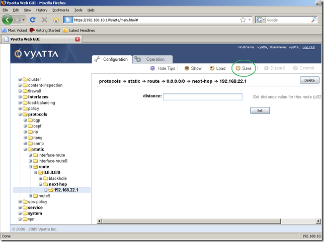
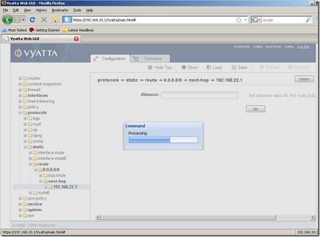
The command is being processed:
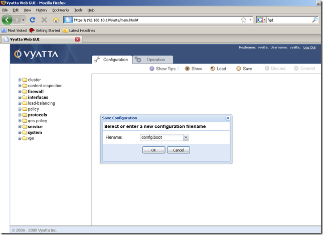
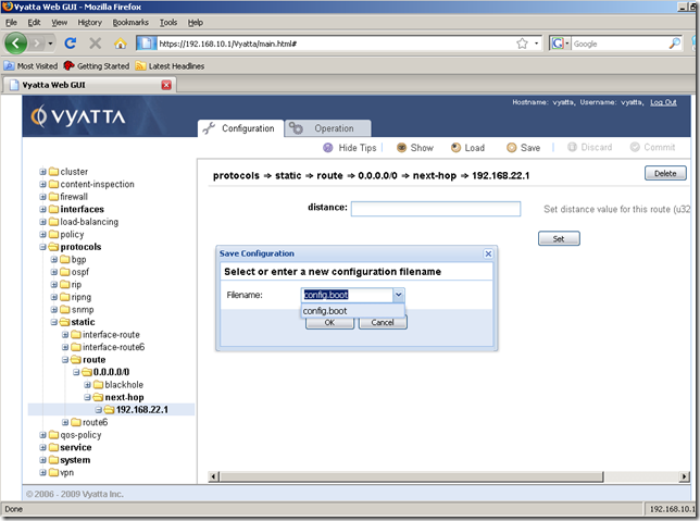
And we are prompted to specify a configuration file. The default one is config.boot, this configuration file will be loaded at boot. It’s fine for us, so click OK:
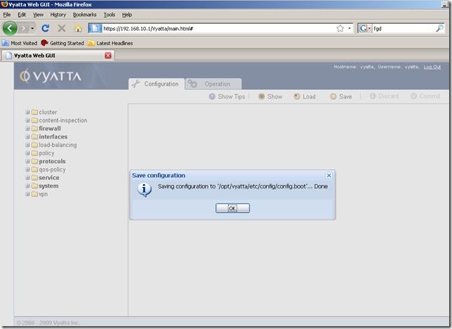
And our configuration was successfully saved:
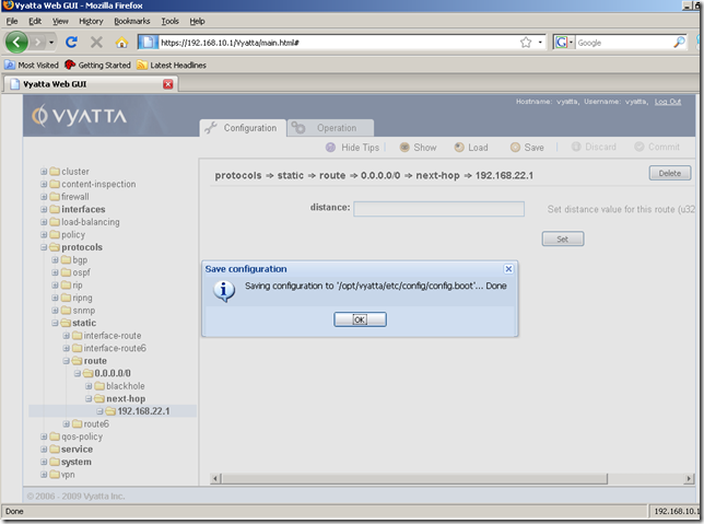
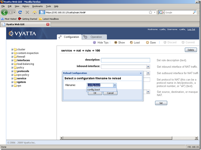
As you have seen, we cannot save the configuration file on our management machine with the Save button. Neither we can load a configuration file from our management machine with the Load command:
Add some firewall rules
As with NAT rules, Vyatta said in their announce that the firewall rules area is to be improved over the time to provide a better way to manage and present the firewall rules.
Say now we want to secure the external interface of this Vyatta machine , which is eth0.
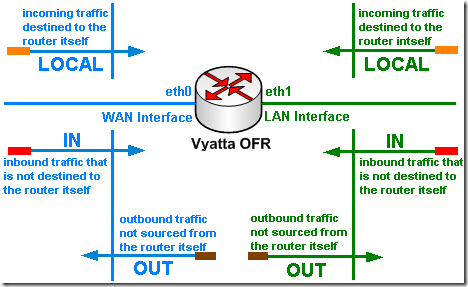
With Vyatta we can apply to an interface firewall instances as: in, out and local.
Since we are talking about Vyatta itself now and its external interface eth0, we are going to use a local firewall instance on eth0.
When applying as local a firewall instance, the firewall will filter packets destined for the Vyatta system itself, as shown bellow:
As you will see, we currently cannot work with firewall objects to simplify management, say to create an object for a DNS server or NTP server, or an object for the internal network, and re-use them within our firewall rules.
First we are going to create a firewall instance, add a few rules to it, then apply this firewall instance as local on the eth0 interface.
So basically we want the router not to respond to ping from the external network, drop any SYN segments that might be used to scan the external interface for open ports etc.
We must be careful with a few things. For example, ping might be used for testing connectivity from the router itself, or the router uses NTP and as an NTP server an external host, or the router needs to resolve a DNS name thus will use DNS to query an external DNS server, or the router may need access to updates(HTTP). Also if you enable the web proxy service on the router you need to allow returning HTTP and HTTPS traffic. Before apply a local firewall instance on an interface, make sure you know what traffic is involved, in order not to block legitimate traffic.
Right now the GUI can be accessed from the external network, when we will finish setting up our firewall rules, the GUI will no longer be accessible from the external network. Of course, if we want this to be possible, we can easily add a firewall rule to allow this, or maybe shrink this firewall rule so just a few external hosts to be allowed to manage this Vyatta using the GUI.
So, for example, due to the nature of the local firewall instance, the echo-requests packets from the router itself to an external destination will be allowed, but echo-replies messages for these packets will be denied. So if we want to be able to ping from the router itself, we need to permit the returning echo-replies messages for the sent echo-requests messages. In a similar way we need to allow NTP, DNS etc. if the connections originate from the router itself.
Let’s create a firewall rule to permit the returning echo-replies messages for the sent echo-requests messages by the router itself.
First thing to do is to create the firewall node:
From the Configuration tab, Navigation area, click the firewall node, and click the Create button:
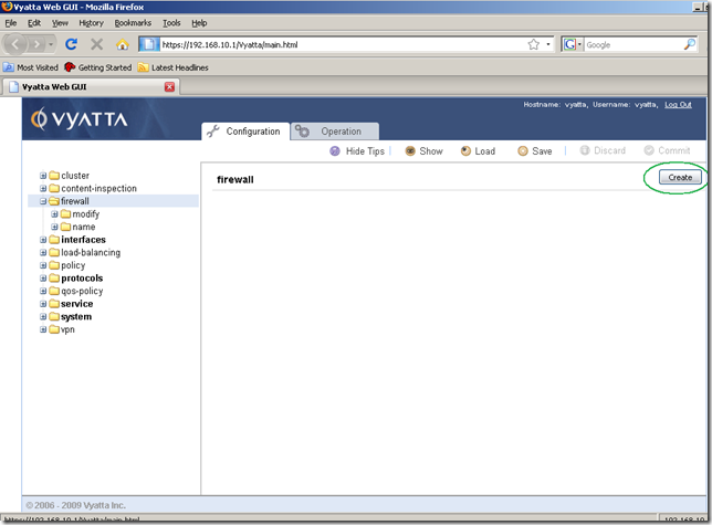
These default settings are fine for us now:
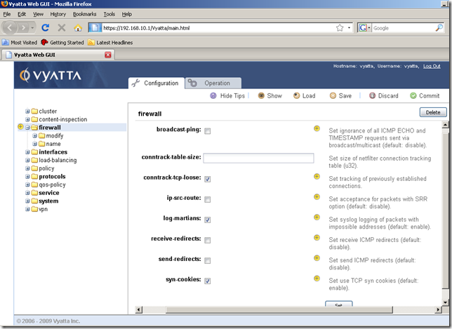
Next we need to create the firewall instance we are going to apply as local on the external interface(eth0).
So click the name sub-node. In the Input/Output area add a name for this firewall instance, say Localeth0, and click the Set button.
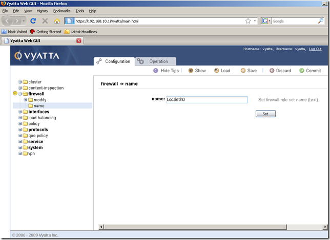
After hitting the Set button, we’re taken automatically to another screen, to set a description for this firewall instance(optional, if we want to):
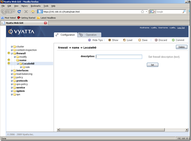
I don’t want to enter a description for this firewall instance right now, so I’ve clicked the rule sub-node to add a firewall rule within this firewall instance, the rule to permit the returning echo-replies messages for the echo-requests messages sent by the router itself. Specified a number for this rule, and click the Set button.
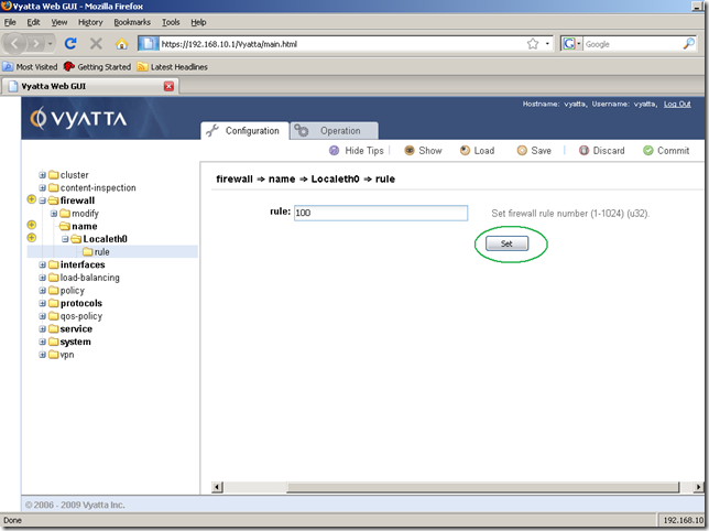
And we’re taken automatically to the rule 100’s properties. Set the action to accept(select it from the drop-down menu) and the protocol to icmp. Click the Set button.
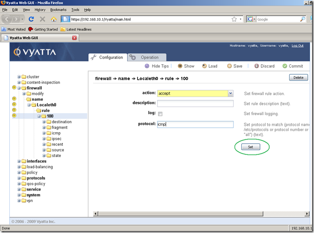
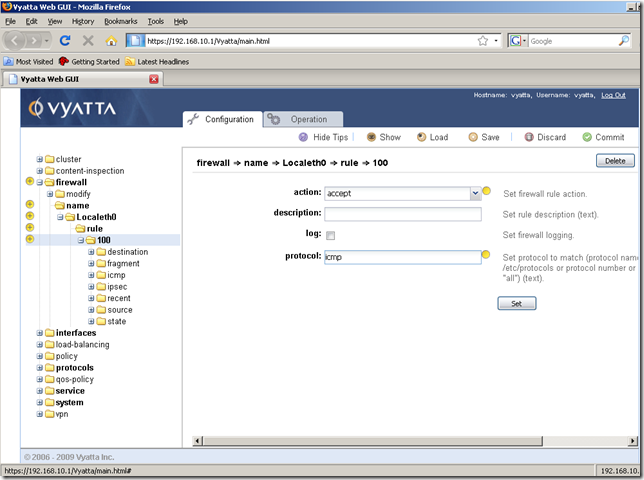
Our settings were set:
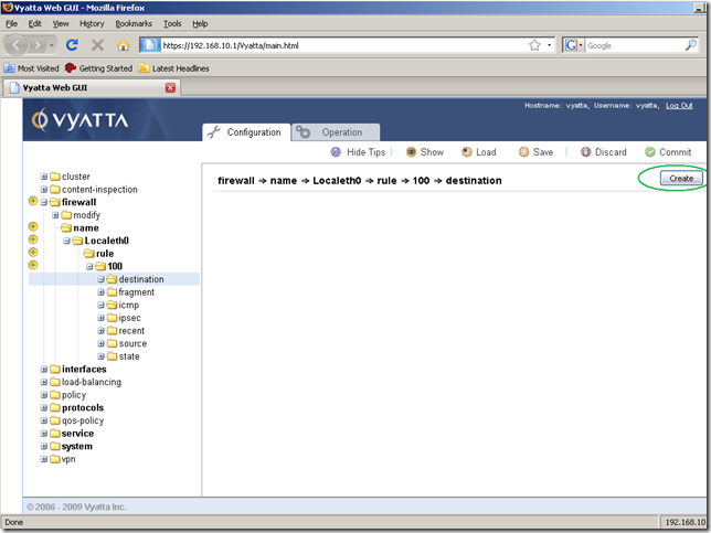
Navigate to the destination sub-node of this rule, and click the Create button:
Now specify the local IP address of the external interface, and click the Set button:
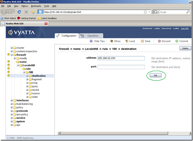
The specified destination was set:
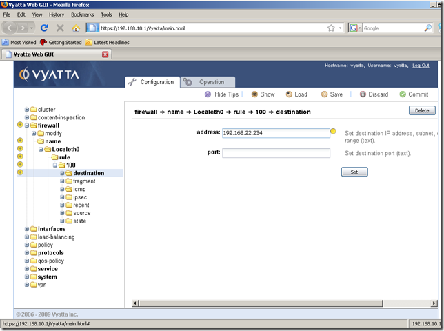
Next click the icmp sub-node of the rule 100, and click the Create button:
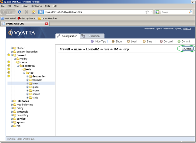
We’re taken automatically to the next screen, where we are going to enter the ICMP code and type corresponding to the ICMP echo-reply message. Click the Set button:
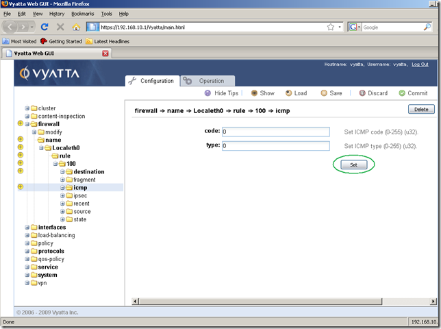
And nothing happens…
A quick work around that I found: set the ICMP code and type to something different than 0, say 1 and 1:
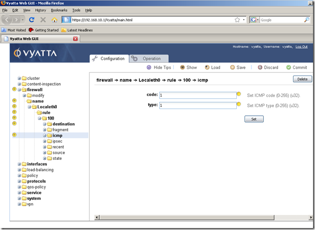
And then set ICMP code and type to 0 and 0 and click the Set button: now the changes are being applied:
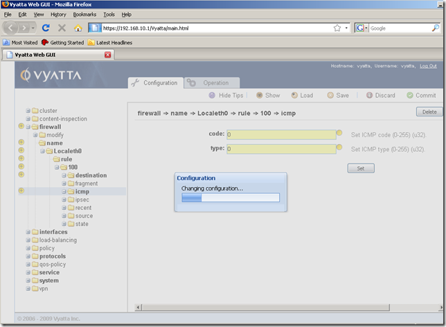
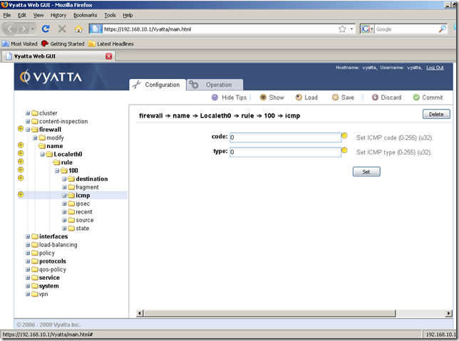
Next move to the state sub-node of the rule 100, and click the Create button:
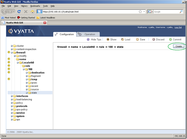
In the screen that appears, check the established and related checkboxes, as the router expects echo-replies messages only for the echo-requests messages sent by it, and click the Set button:
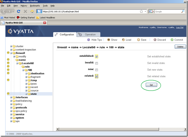
And now, Commit the changes:
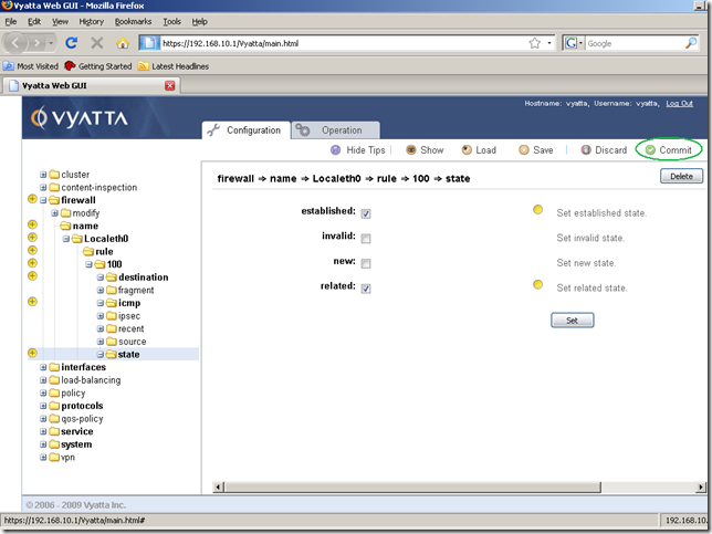
The configuration was applied:
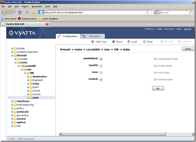
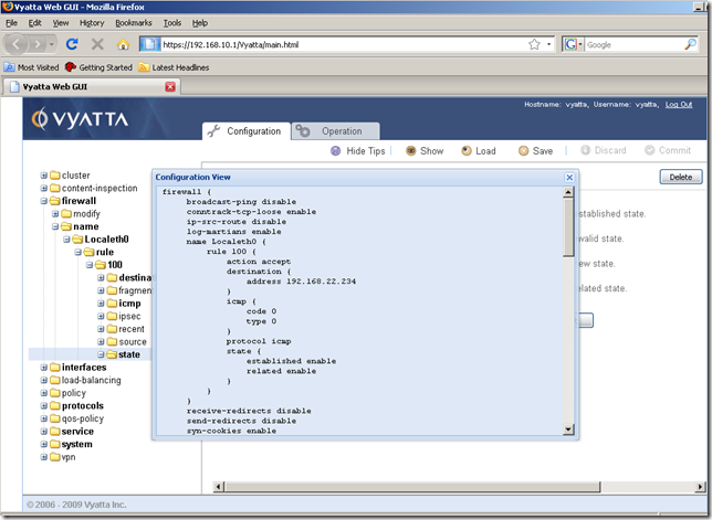
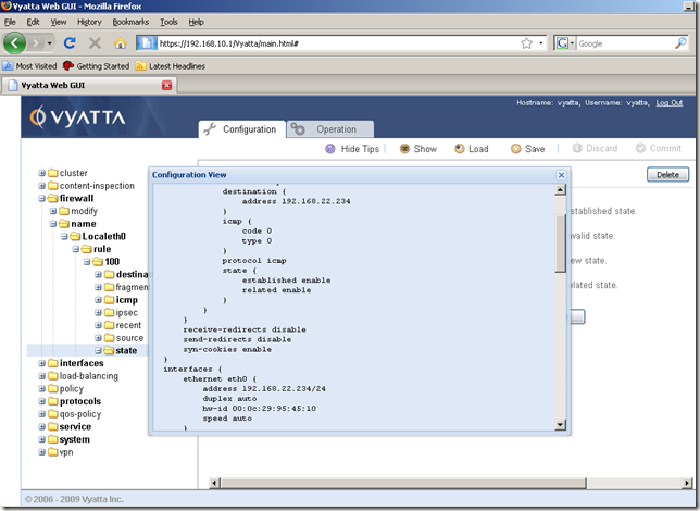
OK. Let’s add a firewall rule allowing NTP now. I’m going to show only the relevant parts this time.
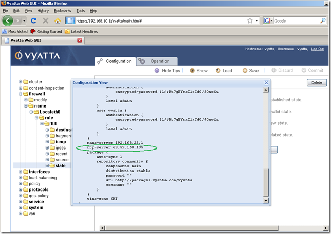
First thing to do, is to check the IP address of the configured NTP server.
We can quickly do that by using the Show command button(which displays the entire configuration of this router) from the Configuration tab:
And additionally we can take at the output produced by the show ntp command in the Operation tab:
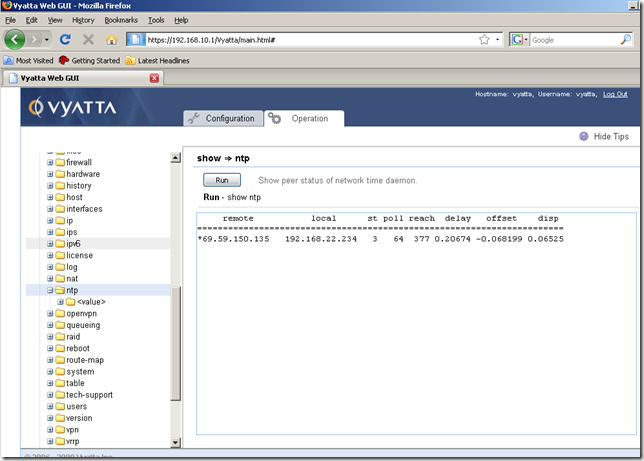
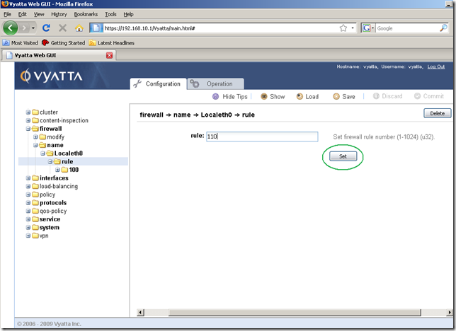
Now we know the IP address of the configured NTP server, so we can go to the Configuration tab, Navigation area, expand the firewall node, expand the name sub-node, expand the created Localeth0 sub-node and click on the rule sub-node. Enter a number for this rule to be added, and click the Set button:
And we’re taken automatically to the rule 110’s properties. Set the action to accept(from the drop-down menu) and the protocol to udp(NTP uses UDP). Click the Set button.
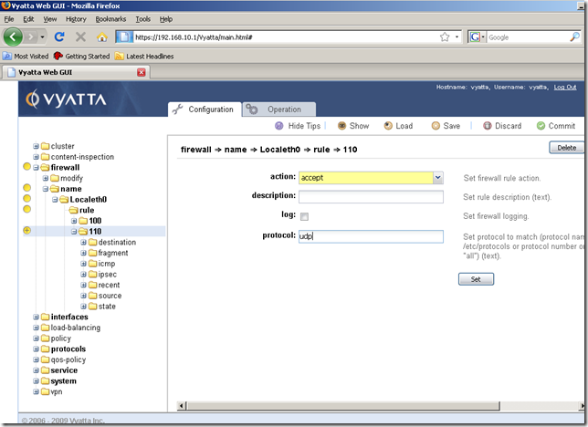
Our settings were set:
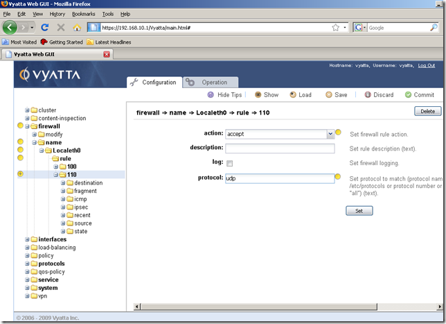
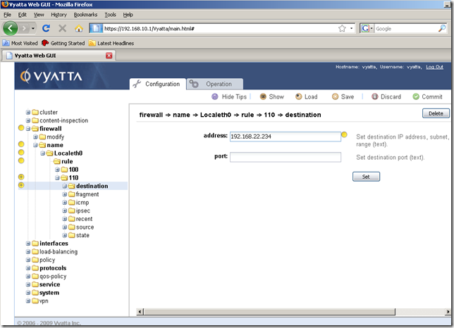
I’ve added as the destination for this rule the local IP address from the external interface eth0:
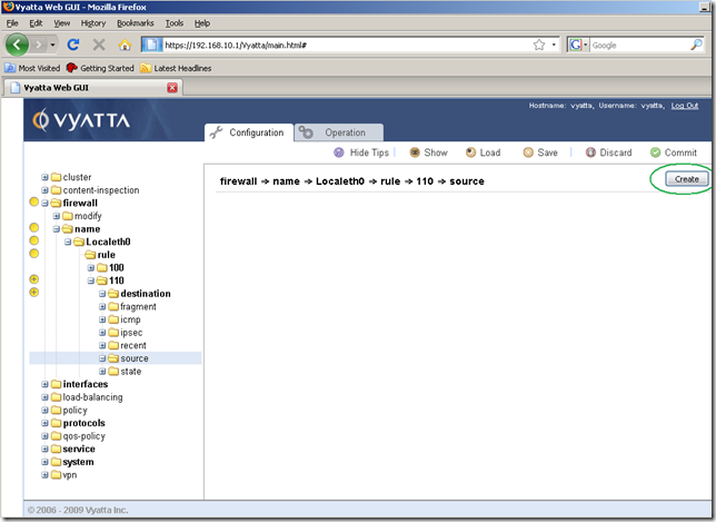
And this time we’re going to add also a source, so click the source sub-node, and click the Create button:
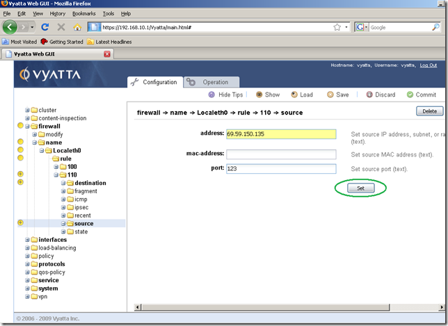
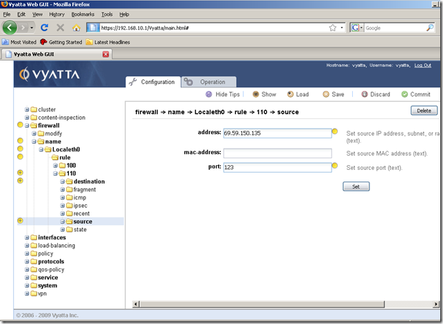
In the Input/Output area add the IP address of the NTP server. Also, the replies packets from the NTP server will be sourced from UDP port 123(the NTP server listens for connections on UDP port 123), so we will add this port as the source port in the Input/Output area. Click the Set button.
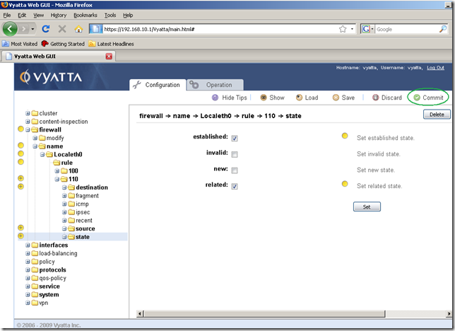
I’ve added a state too, checked the established and related checkboxes, as the router expects replies messages only for the UDP messages sent by it to the NTP server. Then hit the Commit button.
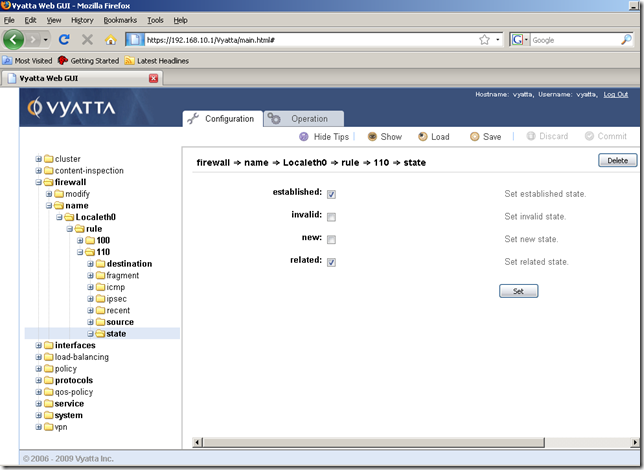
The configuration was applied:
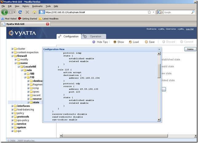
So we’re done with the NTP rule.
In a similar fashion, as UDP is used too, we’re going to add a rule to allow the router to resolve DNS names by using the configured external DNS server.
I’ve added rule 120, which it’s exactly the same as rule 110, except the source node, which is different, the source address is the address of the external DNS server and the source port is 53:
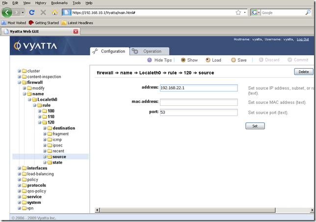
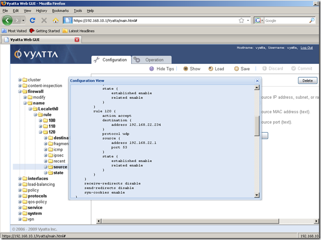
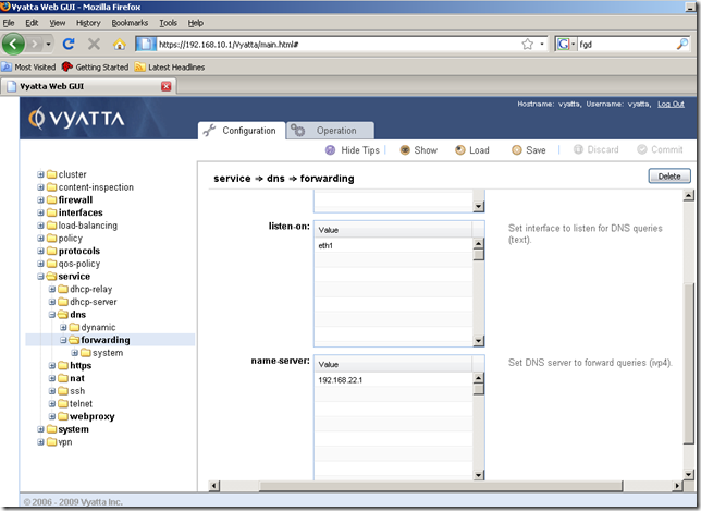
Also note that rule 120 will apply if we use DNS forwarding on Vyatta for the hosts behind Vyatta located on the internal network:
OK. So we’ve added enough firewall rules for now.
It’s time to apply the created firewall instance Localeth0 as local on the interface eth0.
From the Configuration tab, Navigation area, expand the interfaces node, ethernet sub-node, eth0 sub-node, firewall sub-node and click the local sub-node. Click the Create button:
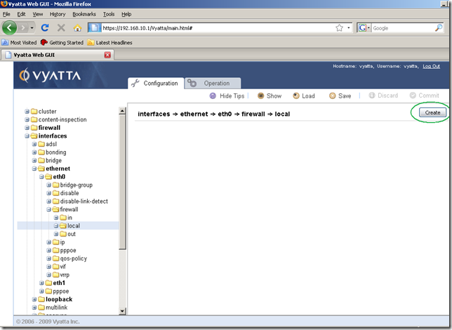
And in the screen that appears, Input/Output area, manually type the name of the firewall instance we want to add. As can be seen, we cannot select the firewall instance we want(I’ve tried to drag the one created, just for fun, in this box but it didn’t work). Click the Set button.
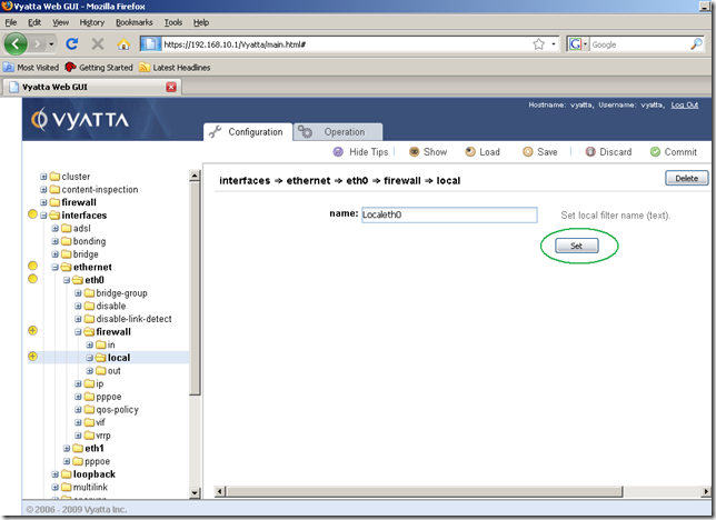
And time to Commit our configuration:
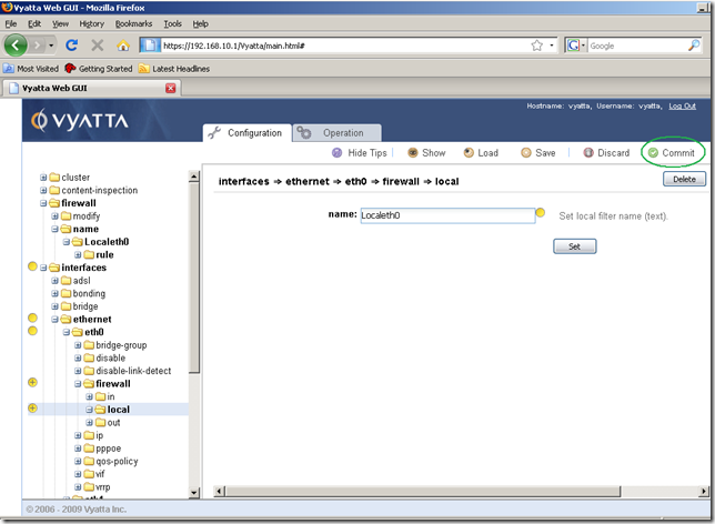
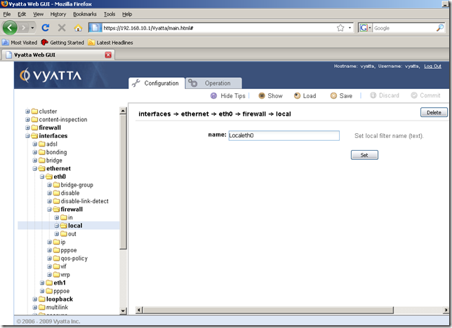
And our configuration was successfully committed, the firewall now starts to filter the specified traffic:
Let’s try to ping a host using its DNS name from this router.
Move into the Operation tab, ping node, and run a ping command:
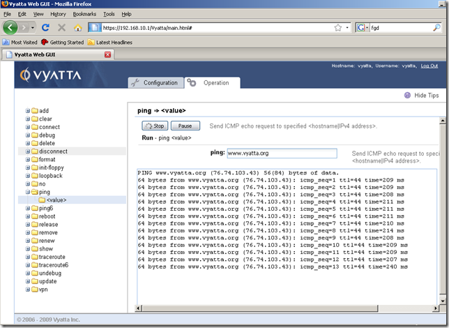
Success.
A quick nmap scan for the external interface eth0 of this router:

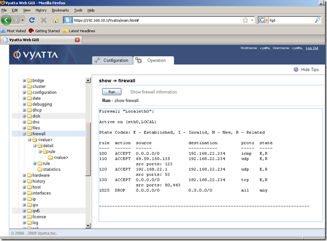
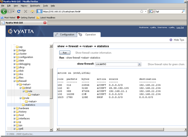
From the Operation tab, show node, firewall sub-node, we can display various info about our firewall instance and firewall rules:
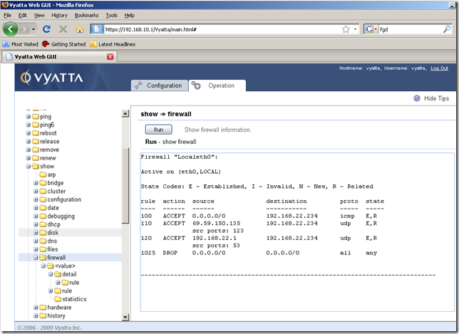
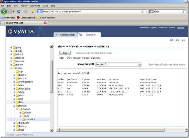
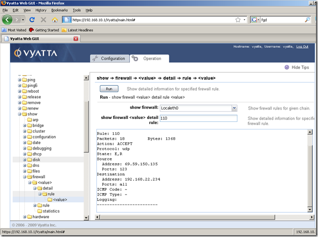
Say I’ve enabled the webproxy service, and the web proxy listens for connections on the IP address of the internal interface eth0, port 8080:
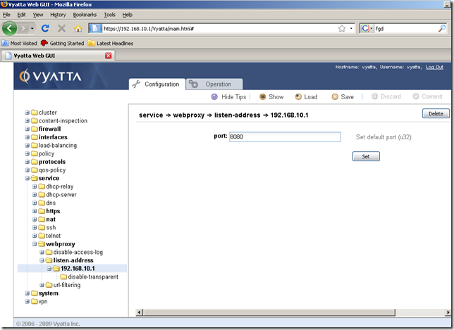
Our current firewall rules from the Localeth0 firewall instance block the proxied web traffic.
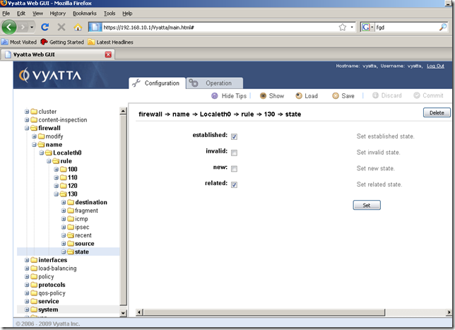
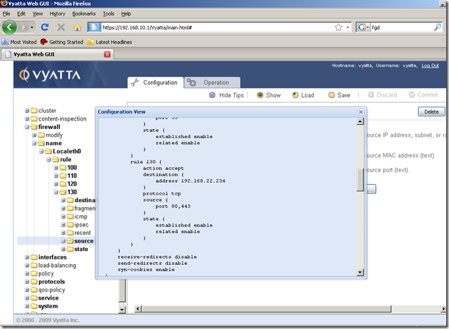
So I’ve added a new firewall rule to the Localeth0 firewall instance, rule 130, to allow this web traffic:
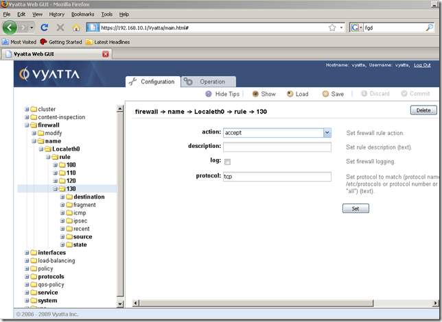
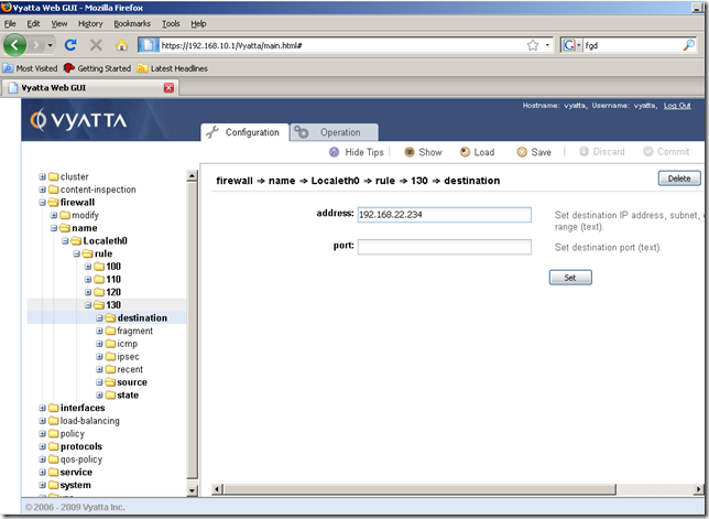
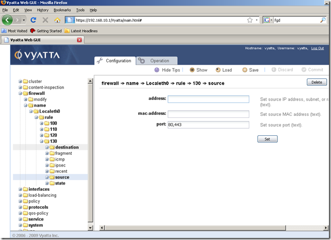
Although the hints don’t tell us this aspect, we can add multiple ports if we want to, see the documentation for more details:
As with the NAT rules, be careful with the numbering of the firewall rules, as you cannot change the number of a firewall rule later.
However we can easily edit the settings of a firewall rule, like source/destination addresses, source/destination ports etc.
Saving the configuration
As we did before, don’t forget to save the configuration, otherwise a reboot will erase any settings unsaved:
