|
03.02.2009
Configure an IPsec Tunnel Mode Site-to-Site VPN between an ISA Server 2006 SP1 SE and a Check Point NGX R65 VPN-1
- 1. Configure the ISA Server 2006 SP1 SE
- 2. Configure the Check Point NGX R65 VPN-1
- 3. Monitor the VPN Tunnel on ISA
- 4. Monitor the VPN Tunnel on Check Point
1. Introduction
In this article we will establish an s2s between an ISA Server 2006 SP1 SE firewall installed on Windows Server 2003 R2 SE SP2 and a Check Point NGX R65 VPN-1.
Figure1 shows the network diagram.
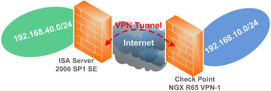
Figure1: Network Diagram
One huge advantage of these two products over similar firewalls, is the fact that both can run in a virtualized environment, like VMware ESX. That means you have a great way to test and fine tune your s2s configurations prior to deployment on your networks.
Microsoft offers for a long time a trial version of ISA Server 2006 SE or EE which is supported in VMware ESX or Hyper-V, and Check Point offers for example a certified VMware ESX VM of their VPN-1 NGX R65 called VPN-1 VE (Virtual Edition).
Please refer to the vendors of these products respective web sites for more details.
Bellow are the IP settings of the two VPN gateways, and the configuration parameters for our s2s VPN connection. The strikethrough IP addresses are not needed, unless you want to ping from the Check Point device without using the -I parameter or so.
ISA Server 2006 SP1 SE
|
External Interface |
192.168.22.240/24 |
|
Internal Interface |
192.168.40.1/24 |
|
Default Gateway |
192.168.22.1 |
|
DNS Server |
192.168.40.2 |
|
VPN Local Subnet |
192.168.40.0/24
192.168.22.240 |
|
VPN Remote Subnet |
192.168.10.0/24
192.168.22.234 |
Check Point NGX R65 VPN-1
|
External Interface |
192.168.22.234/24 |
|
Internal Interface |
192.168.10.1/24 |
|
Default Gateway |
192.168.22.1 |
|
DNS Server |
192.168.10.2 |
|
VPN Local Subnet |
192.168.10.0/24
192.168.22.234 |
|
VPN Remote Subnet |
192.168.40.0/24
192.168.22.240 |
ISA does not support AES, so we are going to use 3DES. Both devices support the stronger DH Group 14(2048-bit), and we are going to use it.
A pre-shared key is used for IKE authentication. Pre-shared keys are very useful for testing, especially if this is the first time when you configure an IPsec tunnel mode s2s between the ISA and a Check Point device, because IKE authentication with certificates may introduce additional issues making troubleshooting more difficult.
1. Configure the ISA Server 2006 SP1 SE
Figure2 shows ISA's networks, and we can spot the Internal Network of ISA.
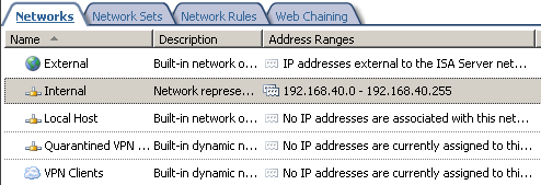
Figure2: ISA - Networks
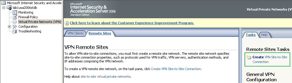
Within ISA's mmc, head over to the VPN Remote Sites panel, see Figure3, and click theCreate VPN Site-to-Site Connection button.
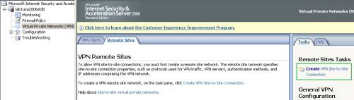
Figure3: ISA - Click Create VPN Site-to-Site Connection
The Create VPN Site-to-Site Connection Wizard appears, on the Welcome window enter a name for this s2s, I've entered Check Point NGX R65 VPN-1, see Figure4.
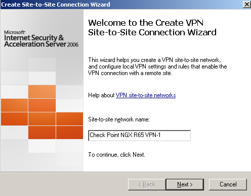
Figure4: ISA - S2S Wizard: Enter The S2S Network Name
On the VPN Protocol window select IP Security (IPsec) tunnel mode, see Figure5.
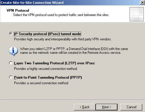
Figure5: ISA - S2S Wizard: VPN Protocol
On the Connection Setings window enter the RemoteVPN Gateways IP address and theLocal VPN Gateways IP address, see Figure6.
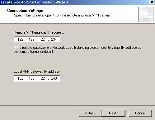
Figure6: ISA - S2S Wizard: Connection Settings
On the IPsec Authentication window select Use pre-shared key for authentication and enter the pre-shared key, see Figure7, (if you decide to use a pre-shared key use a complex and long one, if you decide to use certificates for IKE authentication, you may consider using a dedicated CA to issue certificates just for this s2s connection, since you can specify only from which CA will accept ISA certificates, please refer to my IPsec Tunnel Mode Not Supported Things article).
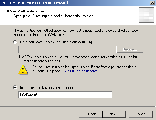
Figure7: ISA - S2S Wizard: IPsec Authentication
On the Network Addresses window enter the VPN remote subnet, in my case 192.168.10.0/24, see Figure8. Note that the remote VPN gateway's IP address was automatically added by the wizard, this is useful when you want to ping directly from the remote VPN gateway, or the VPN traffic(from subnet 192.168.10.0/24) might be NAT-ed(sourced with the remote VPN gateway's IP address) or the remote VPN gateway also acts as a web proxy(say another ISA Server 2006 firewall).
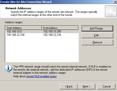
Figure8: ISA - S2S Wizard: Network Addresses
On the Site-to-Site Network Rule window select Create a network rule specifying a route relationship, to create a network rule with a route relationship between the Internal Network and the remote site, see Figure9.
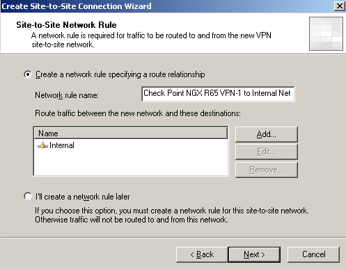
Figure9: ISA - S2S Wizard: Network Rule
On the Site-to-Site Network Access Rule window select Create an allow access rule, to create an access rules that allows All outbound traffic(just for testing) between the Internal Network and the remote site, and vice-versa, see Figure10.
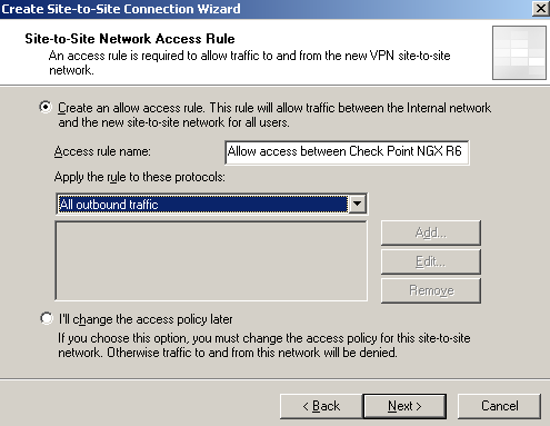
Figure10: ISA - S2S Wizard: Access Rule
Click Finish on the Completing the New VPN Site-to-Site Network Wizard window, seeFigure11.
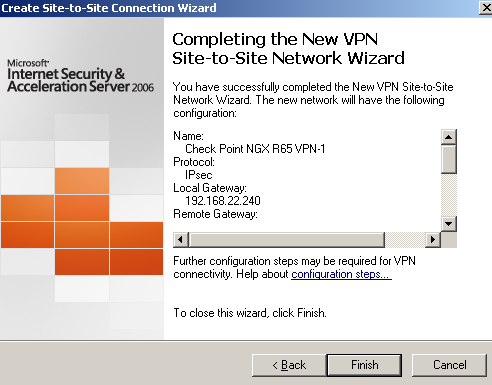
Figure11: ISA - S2S Wizard: Finish
As you have seen, we did not specify any local subnet for our s2s within the s2s wizard, there was no such an option. Scroll another article of mine for more details on this matter.
Do not click Apply yet.
Right-click the newly created remote site, and click Properties, see Figure12.
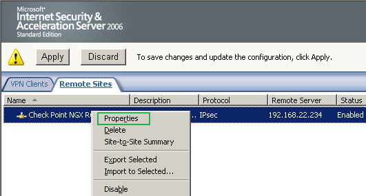
Figure12: ISA - Newly Created S2S: Properties
On the properties windows of the remote site, on the Connection tab, click the IPsecSettings... button, see Figure13.
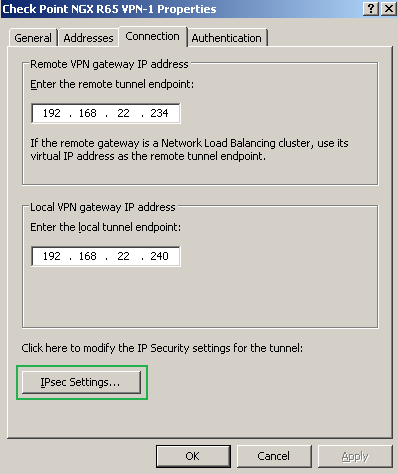
Figure13: ISA - Newly Created S2S: Properties - Connection Tab
On the IPsec Configuration window, on the Phase I tab, we will configure the needed IKE MM settings, see Figure14.
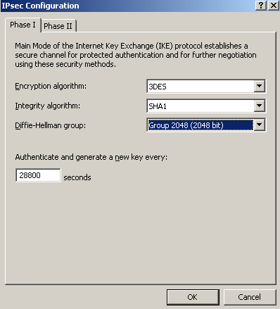
Figure14: ISA - Newly Created S2S: Properties - IPsec Configuration: Phase I
On the IPsec Configuration window, on the Phase II tab, we will configure the needed IKE QM settings, see Figure15.
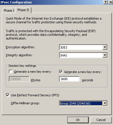
Figure15: ISA - Newly Created S2S: Properties - IPsec Configuration: Phase II
Click OK to close the IPsec Configuration window, and click OK to close the properties of the remote site window.
Right-click the newly created remote site, and click Summary, to visualize the settings summary of this s2s, see Figure16.
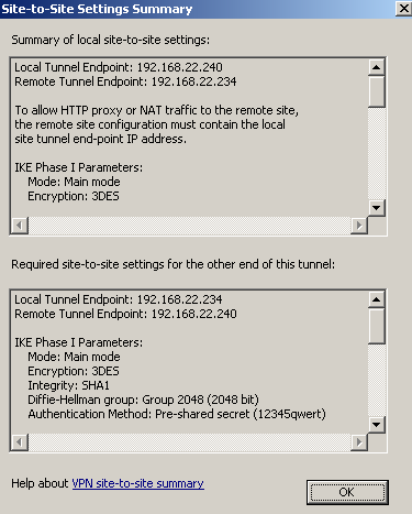
Figure16: ISA - Newly Created S2S: Summary
Click Apply to apply the new settings, see Figure17.
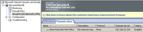
Figure17: ISA - Newly Created S2S
And take a look at the Access Rule and the Network Rule created by the s2s wizard, seeFigure18 and Figure19.
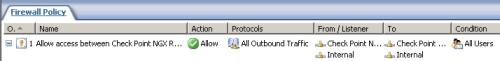
Figure18: ISA - The Access Rule Created by the S2S Wizard
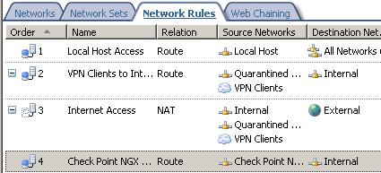
Figure19: ISA - The Network Rule Created by the S2S Wizard
We're done with the configuration of ISA.
2. Configure the Check Point NGX R65 VPN-1
The VPN s2s connection on the Check Point NGX R65 VPN-1 was created using theSimplified Mode, see Figure20 and Figure21.
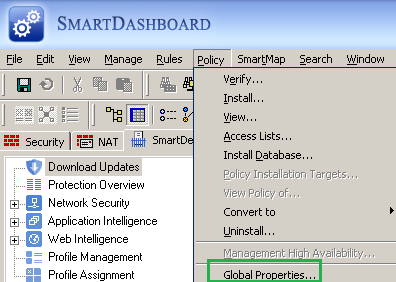
Figure20: Check Point - Policy: Global Properties
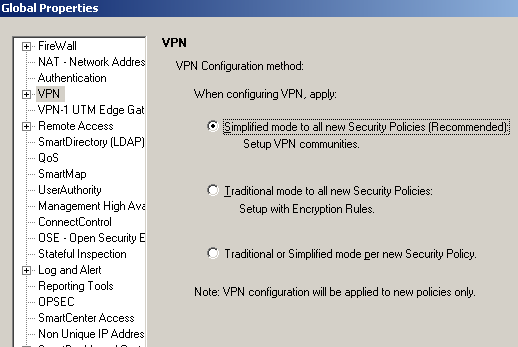
Figure21: Check Point - Policy: Global Properties - VPN
Note: During tests, I've observed a potential issue with the Check Point device when the security policy is configured either using Simplified Mode orTraditional Mode, that is, for example when DH Group 14 was configured on the Check Point for our VPN connection(IKE MM and IKE QM(with PFS)), the Check Point will accept and negotiate IKE MM and IKE QM(with PFS) with a weaker DH Group, like Group 2.
And, in this case, the Check Point device will drop the IPsec ESP traffic, logging the error from Figure60 and Figure61.
However, for example when DH Group 14 was configured on the Check Point for our s2s VPN connection(IKE MM and IKE QM(with PFS)), the Check Point will accept and negotiate IKE MM with a weaker DH Group, like Group 2. Then, if IKE QM(with PFS) is negotiated with DH Group 14, the Check Point device may accept the IPsec ESP traffic.
Or, for example when DH Group 14 was configured on the Check Point for our VPN connection(for IKE MM and no PFS for IKE QM), the Check Point will accept and negotiate IKE MM with a weaker DH Group, like Group 2. Then, IKE QM(without PFS) is negotiated successfully, and after that the Check Point device may accept the IPsec ESP traffic.
I have found that the ICSA Labs Certifications Report for the certified product name VPN-1 Power/UTM NGX Family and product version R65 HFA-30(section Detail Findings-IPsec/IKE Interoperability-), appears to note similar behaviour, and says that SA negotiations with a weaker DH group will not happen if the device is configured using Traditional Mode.
I have found that the "process" also works in reverse, for example if the remote gateway is configured to use the stronger DH Group 14 for IKE MM, and the Check Point device to use the weaker DH Group 2 for IKE MM, the Check Point Device will accept and negotiate IKE MM using the stronger DH Group 14. Or if the remote gateway is configured to use PFS for IKE QM, and the Check Point not, still the Check Point will accept and use PFS for IKE QM.
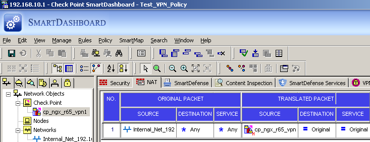
On the Check Point device, I've manually added a test Hide NAT rule, to verify if the VPN s2s traffic is excluded from the NAT process, see Figure22.
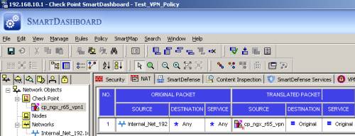
Figure22: Check Point - NAT Policy
Also on the Check Point device, I've added a Network object for the subnet located behind the Check Point VPN gateway, see Figure23. The NAT settings were not defined for this subnet(as I've already manually created a Hide NAT rule).
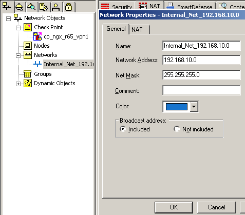
Figure23: Check Point - Network Objects: Internal_Net_192.168.10.0
Edit the Check Point gateway network object(in my case called cp_ngx_r65_vpn1), see Figure24. In the General Properties area, the IP address of this gateway corresponds to the IP address from its external interface, and the VPN product is selected, see Figure24.
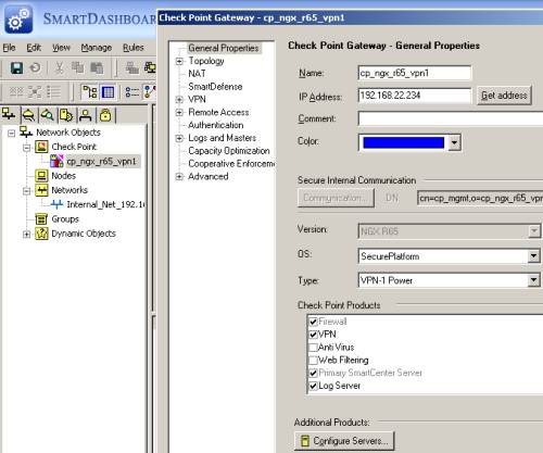
Figure24: Check Point - Network Objects: cp_ngx_r65_vpn1 - General Properties
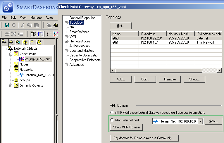
In the Topology area, I've configured the topology in respect with the ethernet interfaces, and Manually defined the VPN Domain, to specify the local subnet behind the Check Point, see Figure25.
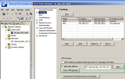
Figure25: Check Point - Network Objects: cp_ngx_r65_vpn1 - Topology
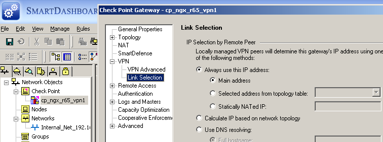
The VPN settings are untouched, for example see the Link Selection area from Figure26.

Figure26: Check Point - Network Objects: cp_ngx_r65_vpn1 - VPN: Link Selection
We're done editing the Check Point gateway network object.
From the SmartDashboard interface, click the Manage menu, and select Network Objects, see Figure27.
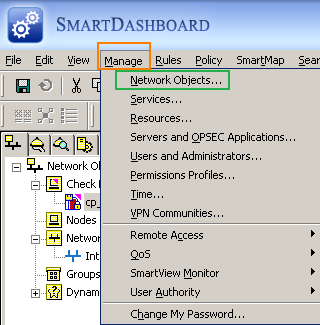
Figure27: Check Point - Manage Network Objects
On the Network Object window, click the New button and click Network, see Figure28.
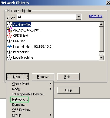
Figure28: Check Point - Manage Network Objects: New Network
We will define for this new Network the subnet behind the ISA VPN gateway, see Figure29. The NAT settings were not defined for this subnet. Click OK to add the new Network.
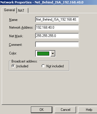
Figure29: Check Point - New Network Object: Net_Behind_ISA
Now, on the Network Object window, click the New button and click Interoperable Device..., see Figure30.
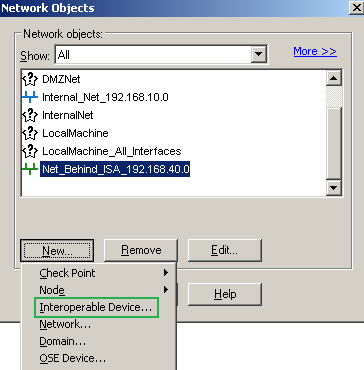
Figure30: Check Point - Manage Network Objects: New Interoperable Device
The Interoperable Device represents our ISA VPN gateway. On the General Propertiesarea of this Interoperable Device, enter a suggestive name and specify ISA's external IP address, see Figure31.
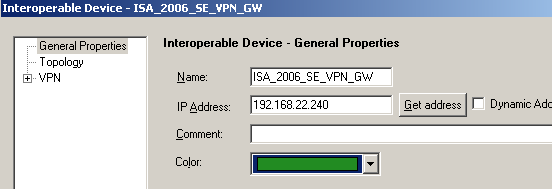
Figure31: Check Point - New Interoperable Device: ISA_2006_SE_VPN_GW
On the Topology area of this Interoperable Device, I've Manually defined the VPN Domain, see Figure32.
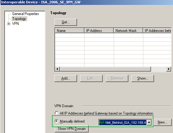
Figure32: Check Point - New Interoperable Device: ISA_2006_SE_VPN_GW - Topology
The VPN settings are untouched, for example see the Link Selection area from Figure33.
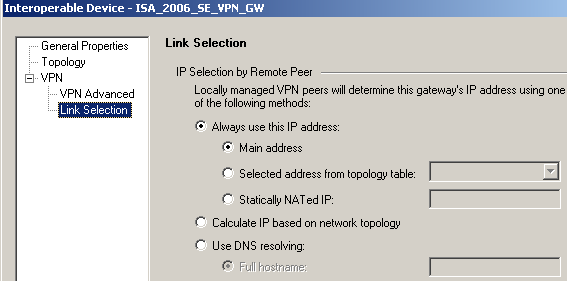
Figure33: Check Point - New Interoperable Device: ISA_2006_SE_VPN_GW - VPN Link Selection
Click OK to add this new Interoperable Device, and click Close to close the Network Objects window, see Figure34.
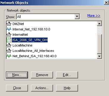
Figure34: Check Point - Manage Network Objects: New Interoperable Device
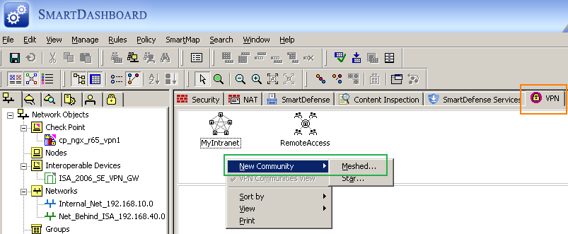
On the SmartDashboard, within the VPN manager panel, right-click the area and click New Community - Meshed, see Figure35.
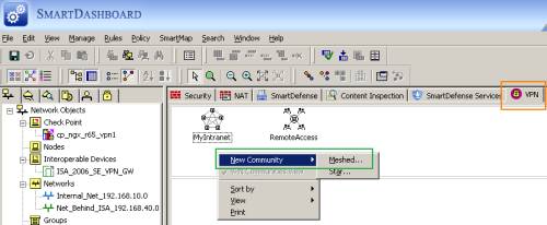
Figure35: Check Point - VPN: New Community - Mesh
And we will add the ISA_Community Meshed Community, see Figure36. If we select theAccept all encrypted traffic option, a security rule will be automatically added for us for this community, see Figure43. If we do not select this option, we will manually define some security rules for our VPN s2s traffic, see Figure44.
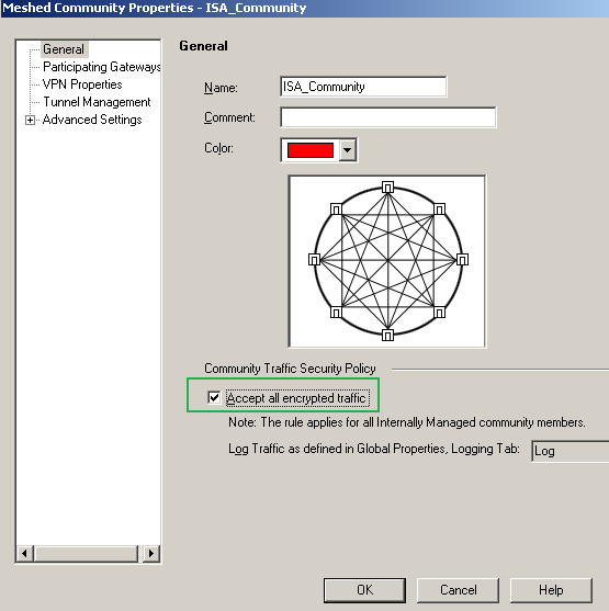
Figure36: Check Point - VPN: ISA Community
Add the participating VPN gateways for the ISA_Community, see Figure37.
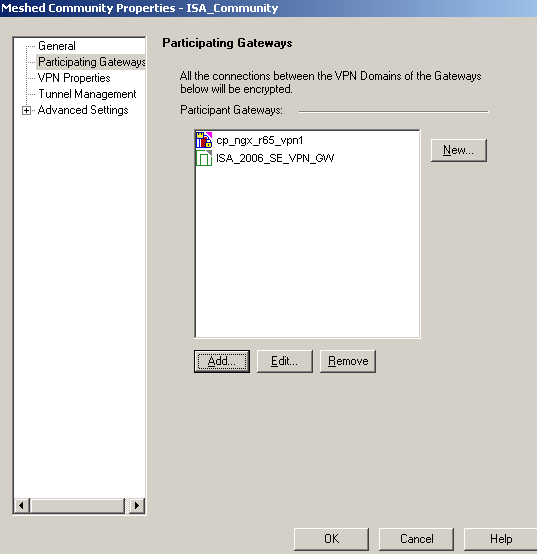
Figure37: Check Point - VPN: ISA Community - Participating Gateways
In the VPN Properties area, specify the IKE(Phase 1 Properties) and the IPsec(Phase 2) Properties, see Figure38.
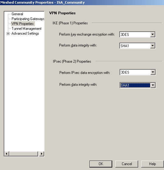
Figure38: Check Point - VPN: ISA Community - IKE and IPsec Properties
I didn't modify the Tunnel Management settings, see Figure39.
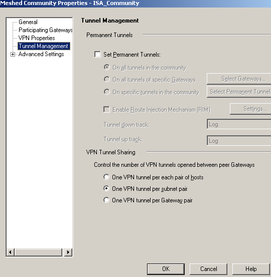
Figure39: Check Point - VPN: ISA Community - Tunnel Management
Since we are using a pre-shared key for authentication, within the Advanced Settings/Shared Secret area, we will add the required pre-shared key, see Figure40.
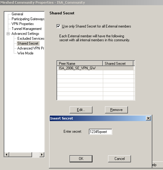
Figure40: Check Point - VPN: ISA Community - Shared Secret
Within the Advanced Settings/Advanced VPN Properties area, we will configure theIKE(Phase I) and IPsec(Phase 2) needed settings, see Figure 41. Also we will Disable NAT inside the VPN community.
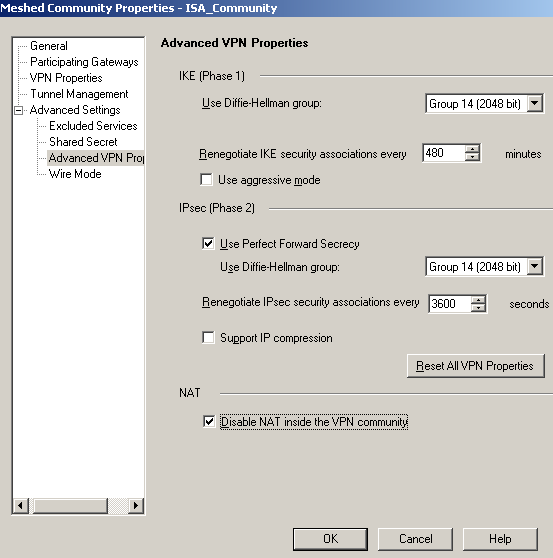
Figure41: Check Point - VPN: ISA Community - Advanced VPN Properties
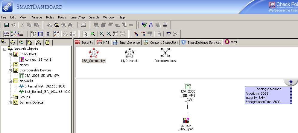
Click OK to add this new VPN Community, see Figure42.
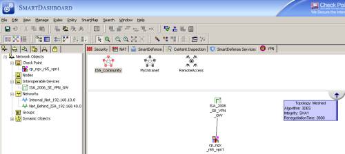
Figure42: Check Point - VPN: Newly Created ISA Community
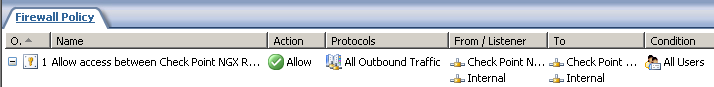
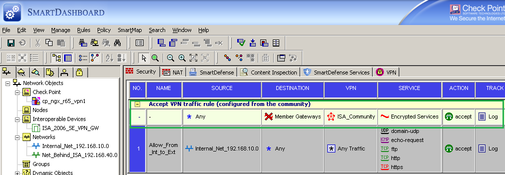
If you selected the Accept all encrypted traffic option, a security rule was automatically added for you for this community, see Figure43.
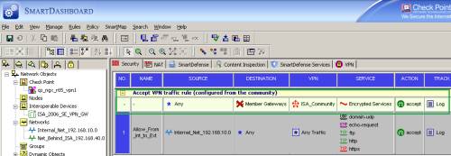
Figure43: Check Point - Security: Added Rule from the Community
If you didn't select the Accept all encrypted traffic option, add now some security rules, seeFigure43. I've added three rules there. I could have combined rules 1 and 2 into one rule. Also note that I've added a third security rule, allow VPN traffic from ISA itself to the subnet behind the Check Point VPN gateway. This rule is needed to allow the web proxied traffic by ISA. Since ISA acts as a proxy, the web traffic(including the HTTP one of SecureNAT clients) from the host behind ISA to hosts behind the Check Point, will be sourced with ISA's external IP address. To avoid this see Tom Shinder's Quick Review - Configure Sites for Direct Access, or if you have only SecureNAT clients behind ISA, you can create a custom HTTP protocol with the Web Proxy unbound from this protocol, and then create, in this order, an allow rule for this custom protocol and a deny rule for the "normal" HTTP protocol for HTTP traffic between the hosts behind ISA to hosts behind the Check Point. You may consider twice before excluding the HTTP the traffic between the hosts behind ISA to hosts behind the Check Point from ISA's HTTP application filter's inspection, as it may decrease your level of security.
As you can note, this third rule also allows echo-requests too, just in case you want to test from ISA itself, although this is pretty meaningless, because, due to IPsec tunnel mode, testing from ISA itself, you will endup with a SA for the 192.168.22.240 and 192.168.10.0/24 proxy ids, and to actually allow the traffic between the hosts behind ISA to hosts behind the Check Point and vice-versa you need SAs for the 192.168.40.0/24 and 192.168.10.0/24 proxy ids.
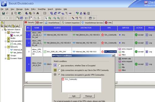
Figure44: Check Point - Security: Manually Added Rules
And finally install the created security policy on the Check Point, see Figure45.
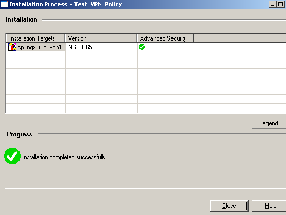
Figure45: Check Point - Policy Installed Successfully
3. Monitor the VPN Tunnel on ISA
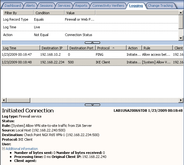
We can use the Live Logging on ISA to monitor the traffic between sites. From example, fromFigure46, we can see that the VPN tunnel was initiated from a host behind ISA by using the ping command, and thus IKE traffic was allowed by ISA, using the required system policy rule.
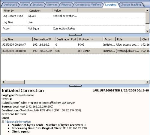
Figure46: ISA MMC Logs - IKE Traffic
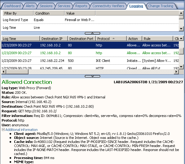
In Figure47 and Figure48 we can spot allowed HTTP traffic from a host behind ISA to a host behind Check Point and vice-versa.
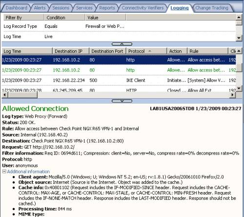
Figure47: ISA MMC Logs - HTTP Traffic from a host behind ISA to a host behind Check Point
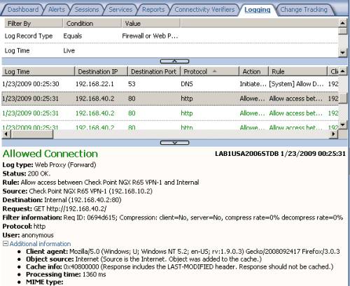
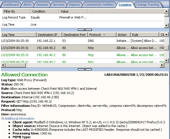
Figure48: ISA MMC Logs - HTTP Traffic from a host behind Check Point to a host behind ISA
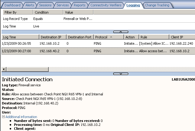
In Figure49 we can spot allowed ping traffic from a host behind ISA to a host behind Check Point and vice-versa.
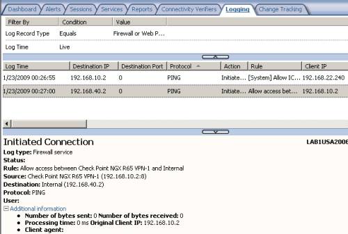
Figure49: ISA MMC Logs - Ping Traffic from a host behind ISA to a host behind Check Point and vice-versa
In the session area, we can notice that a Session Type VPN Remote Site exists, seeFigure50.
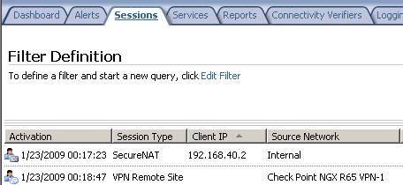
Figure50: ISA MMC - Sessions: VPN Remote Site
However, all this stuff from ISA's mmc does not tell us much about the VPN tunnel itself. For that we can use the IP Security Monitor mmc.
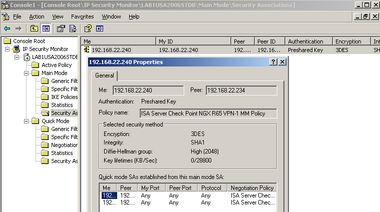
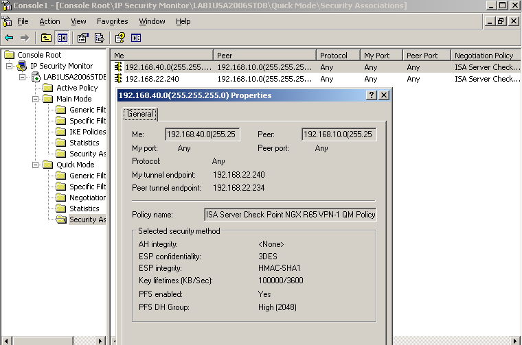
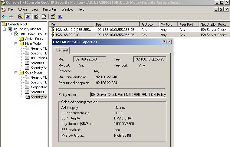
The IP Security Monitor mmc will give us a lot of information about the VPN tunnel, like the existing IKE MM SA, IKE QM SAs, statistics, see Figure51, Figure52 and Figure53. For example, from Figure53, we can see that IKE QM SAs exist for the proxy ids 192.168.22.240(ISA itself) and subnet 192.168.10.0/24(the subnet behind the Check Point), these SAs are needed to allow HTTP traffic proxied by ISA from hosts behind ISA to hosts behind the Check Point.
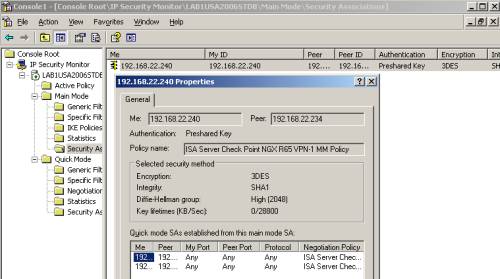
Figure51: ISA IP Security Monitor MMC - IKE MM SA
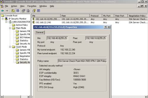
Figure52: ISA IP Security Monitor MMC - IKE QM SA proxy ids 192.168.40.0/24 and 192.168.10.0/24
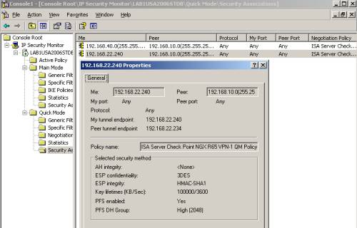
Figure53: ISA IP Security Monitor MMC - IKE QM SA proxy ids 192.168.22.240/32 and 192.168.10.0/24
Or if you like the cmd, you can use the netsh commands to display various information about the VPN tunnel, like the existing IKE MM SA, IKE QM SAs..., see Figure54 and Figure55.
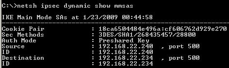
Figure54: ISA - netsh ipsec dynamic show mmsas
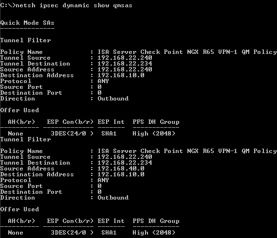
Figure55: ISA - netsh ipsec dynamic show qmsas
Monitor the VPN Tunnel on Check Point
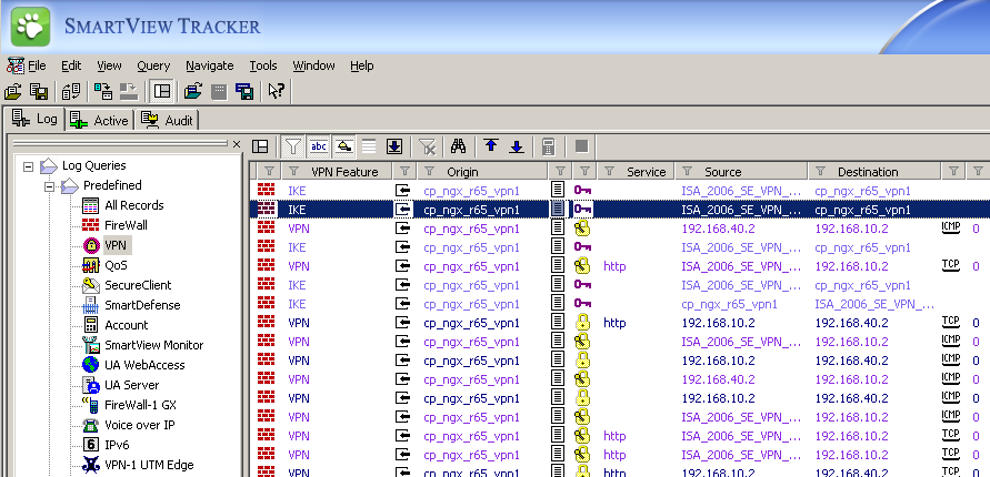
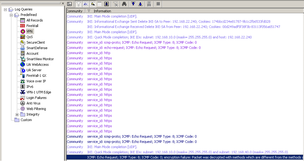
On the Check Point we can use the SmartView Tracker to monitor the VPN tunnel, find details about the IKE negotiations, and view the data traffic between the two sites, see Figure56, Figure57 and Figure58.
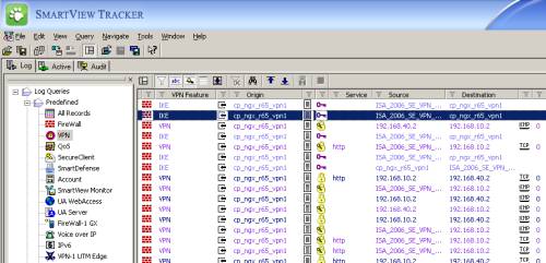
Figure56: Check Point SmartView Tracker - VPN
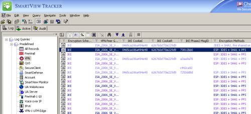
Figure57: Check Point SmartView Tracker - VPN: IKE Cookies
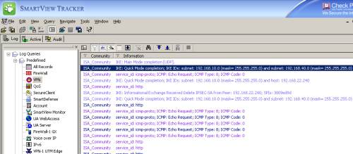
Figure58: Check Point SmartView Tracker - VPN: IKE MM and QM Negotiations + Encrypted/Decrypted Data
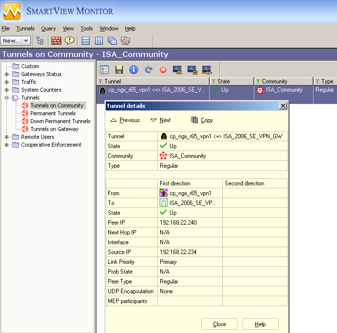
We can use the SmartView Monitor to get some info about the VPN tunnel, see Figure59.
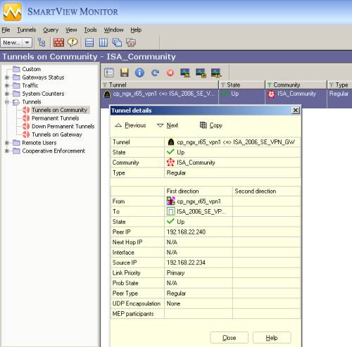
Figure59: Check Point SmartView Monitor - Tunnels on Community
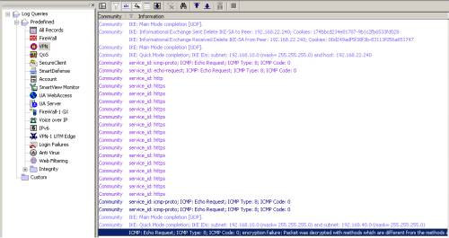
Figure60: Check Point SmartView Tracker - Dropped Packet due Encryption Failure
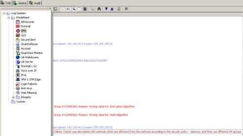
Figure61: Check Point SmartView Tracker - Dropped Packet due Encryption Failure: Wrong DH Groups
|